Calibration#
The calibration mode is divided into two sections (see fig) , at the top, there are three sliders that allow the user to manually set the vertical frontal galvo, the vertical lateral galvo, and the piezo. Below there are two buttons to add or remove a calibration point. And at the bottom, there is another section for activating the noise subtraction function. The calibration routine works as follows:
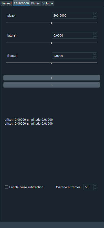
Fig. 7 Sashimi calibration mode GUI#
The calibration routine works as follows (see also the schematic):
Firstly, you cover one laser beam (either the frontal or lateral).
Move the piezo into a position.
Adjust the non-covered laser beam with the corresponding vertical galvo slider until the image in the viewer is sharp enough.
Cover the other laser and adjust the non-covered laser beam with the corresponding vertical galvo slider until the image in the viewer is sharp enough.
Add the calibration point with the button.
Repeat for multiple piezo positions.
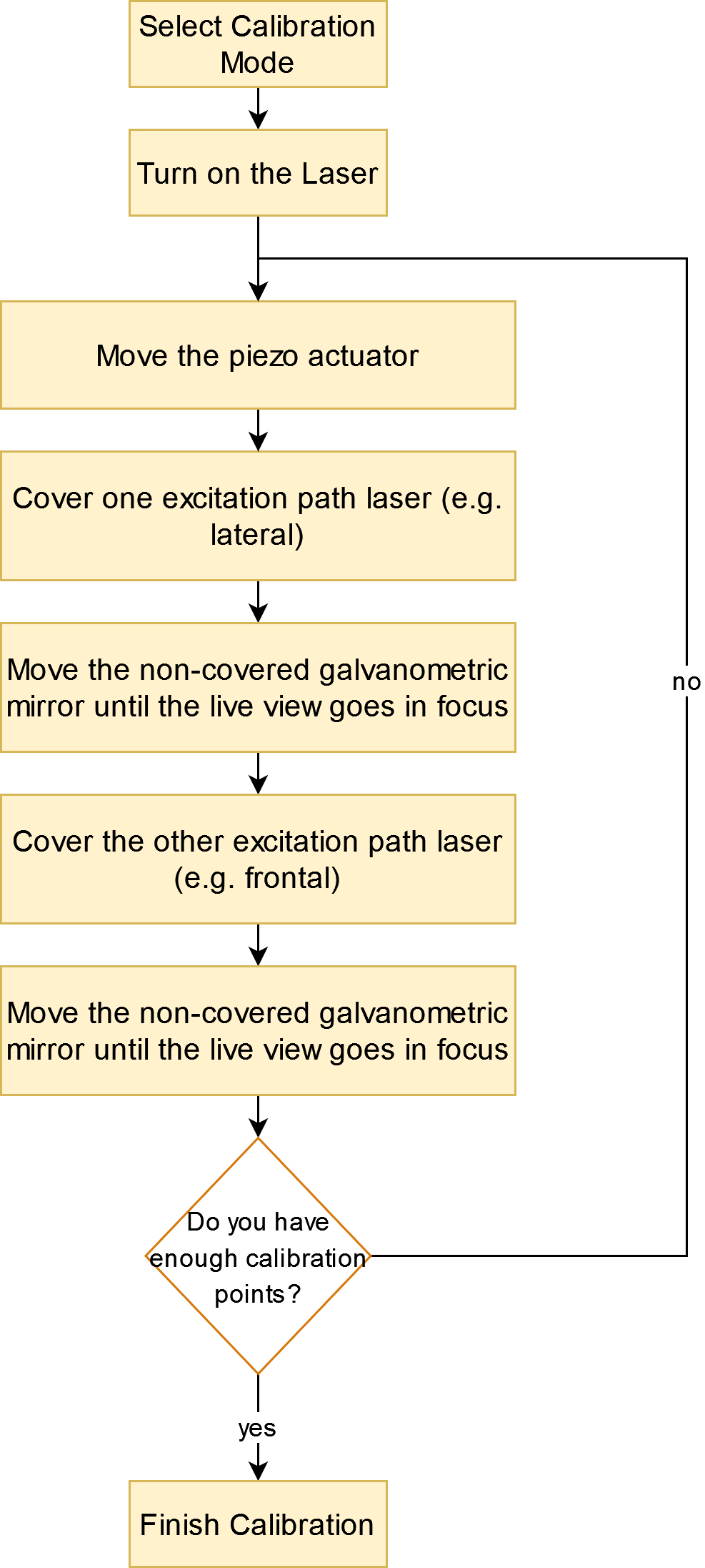
Fig. 8 Sashimi calibration workflow#
To choose the piezo position two things are important:
it is best if the piezo position used for the calibration includes the vertical scanning range that will be set in the volumetric mode
the minimum number of calibration points is three, but the more are present the more accurate the calibration will be. The software will try to fit a linear function to the points, so the more points the more accurate the estimate will be.
The second section of the calibration mode allows the user to activate a noise subtraction filter. Once it is activated a pop-up will ask the user to turn off all the lights and the software will take an n number of images to compute the average sensor noise. This is then saved and subtracted to all the following acquired frames (see the figure).
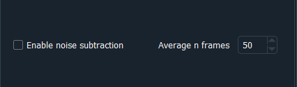
Fig. 9 Sashimi lower part of the calibration GUI#