Microscope Hardware#
Sashimi was built for a two-beam digitally-scanning lightsheet microscope used for brain imaging zebrafish larvae and drosophila.
Digitally Scanned Light-sheet Microscopy (DLSM)#
Light sheet fluorescence microscopy (LSFM) is a microscopy technique that uses a thin sheet of light to illuminate a fluorescent sample. The main advantages of this technique are the high resolution in z, thanks to the optical sectioning of the sample, and that it decreases the bleaching of fluorescent samples since not all the fluorophores of the sample are excited at the same time. In a digitally scanned light-sheet microscope the light sheet is created by moving a laser beam horizontally hundreds of times per second (normally at a frequency between 200Hz and 1kHz). The sheet of light can then be moved vertically to acquire volumetric data.
The overall simplified structure consists of a laser beam, which is split into two separate beams, and sent to multiple mirrors until it is redirected to two galvanometric mirrors (see the excitation path setup in figure). This structure is specific to our setup since we need two excitation paths in order to image the whole brain of a zebrafish while trying not to hit the eyes with the laser beam. This can be easily achieved with two sheets of light, one coming from the front of the fish and the second one coming from the side.
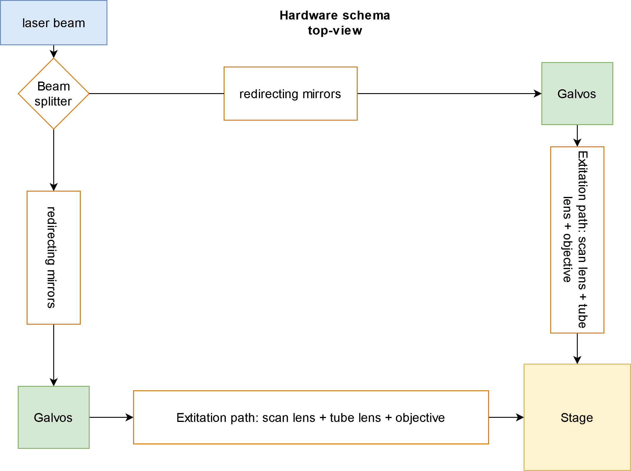
Fig. 14 Sashimi excitation paths#
Each side has two galvanometric mirrors which can move the beam horizontally and vertically. The horizontal motion generates the light sheet, while the vertical one moves the light sheet across the sample. After the galvanometric mirrors, the beam of light goes through multiple lenses to collimate and expand the beam and finally passes through an objective. The point where the waist of the beam is the thinnest is the optimal location at which to construct the imaging path. It is important to note that both beams should meet and align where the waist is thinnest (see fig) since that is where the maximum z-resolution can be achieved.
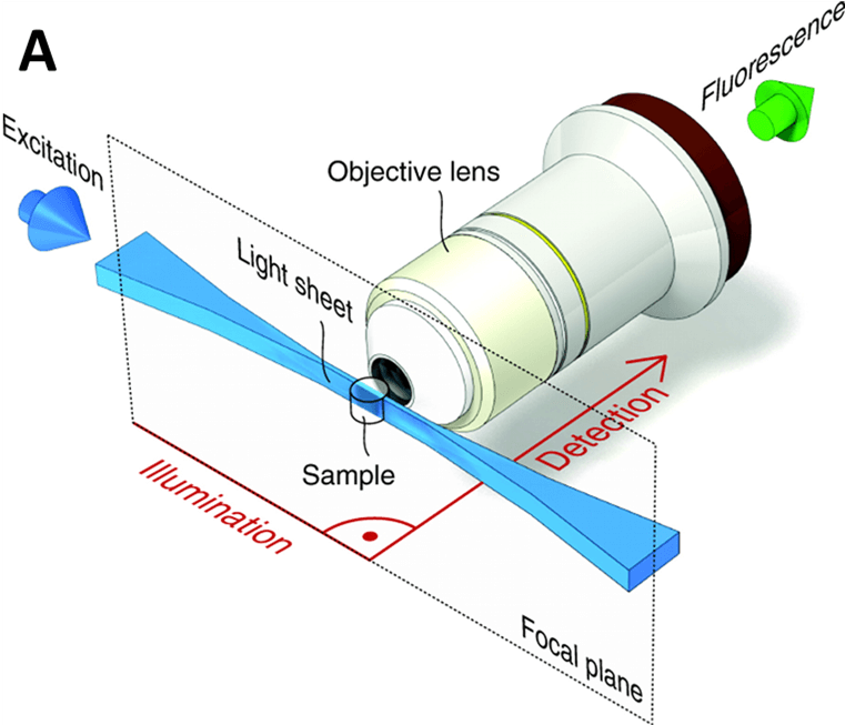
Fig. 15 A simple example of a ligth-sheet setup [3]#
The imaging path comprises a camera, tube lens, imaging objective, piezo, and filter. The camera, tube lens, and objective must be at a constant distance relative to each other (the distance depends on the focal distance of the tube lens) and are therefore mounted on a fixed railing system that can be moved as a whole piece. The GFP filter ensures that only the photons at the right wavelength are collected by the camera, and consequently filters out any unwanted noise. The piezo allows the objective to move vertically in a synchronized way with the galvanometric mirrors, generating the vertical scanning of the sheet of light (see fig). This synchronous motion ensures that the sheet of light and the focal plane of the camera are always matching.
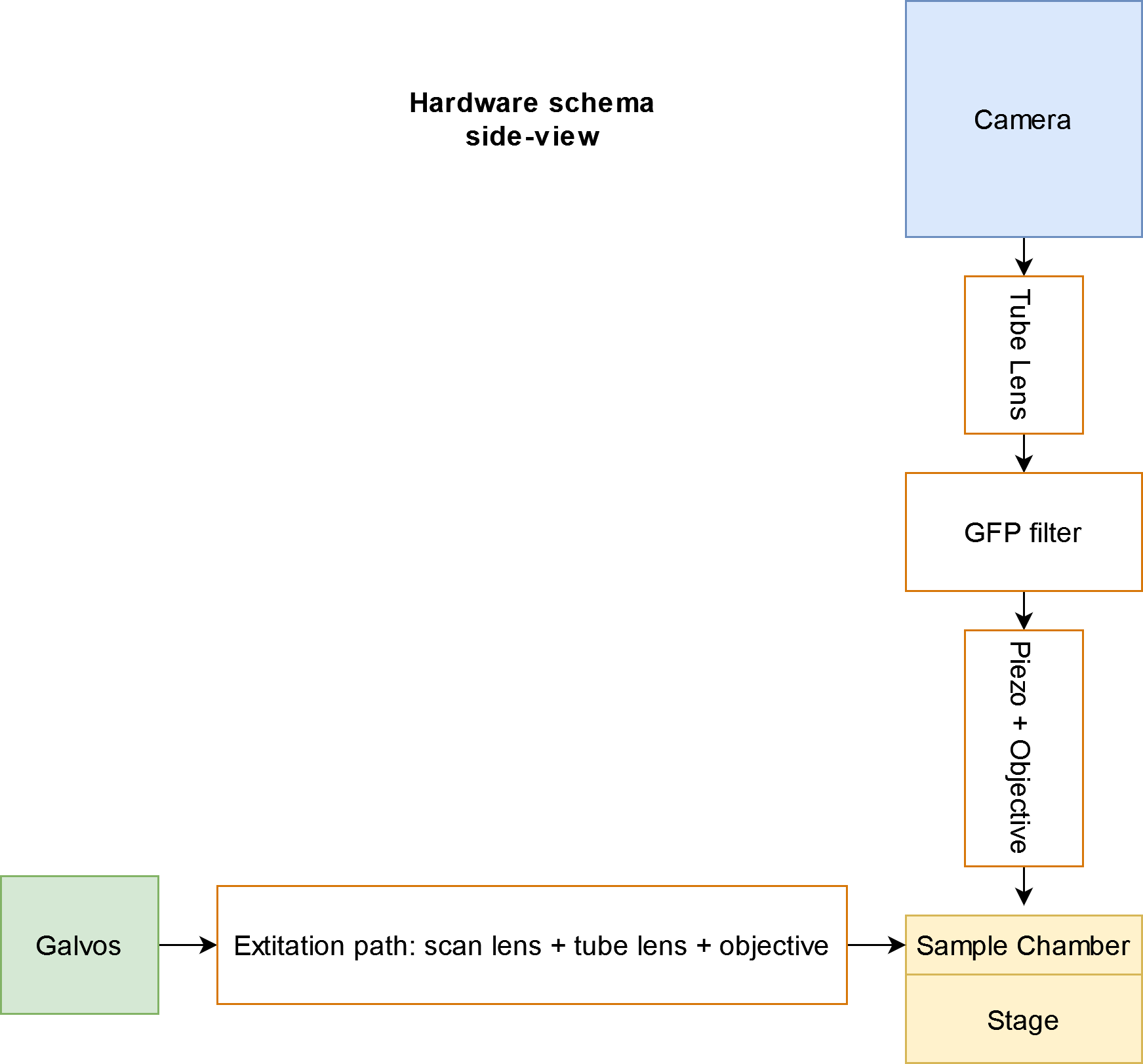
Fig. 16 Simplified schematic of the the imaging path and one excitation path of a light-sheet#
Hardware Components#
The main components of a light-sheet are the camera, galvanometric mirrors, laser beam, lenses, objective, piezo-objective positioner, GFP filter, and stage.
Camera#
The camera we used for our implementation is the ORCA Flash 4 from Hamamatsu. It allows for fast imaging acquisition, in combination with a large sensor that can acquire large field images. Depending on the frame size the camera can achieve various frequencies (see table).

Fig. 17 Hamamatsu camera specifications#
Galvanometric mirrors#
Galvanometric mirrors (see fig and fig) are used to move the laser beam both vertically and horizontally. The horizontal fast motion (200-1000Hz) generates a light sheet, while the slow vertical motion (1-20Hz) allows for volumetric imaging. Being a two-beam light-sheet, there are two excitation light paths (frontal and lateral) from which the sample is illuminated.
Therefore, there are four galvanometric mirrors, two of which are bigger in size and are used for slower motion, and two that are smaller and move at faster speeds. Each side has one of a kind, the bigger one for vertical motion and the smaller one for horizontal motion.
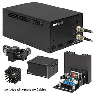
Fig. 18 Galvanometric mirror controller#
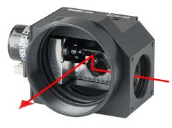
Fig. 19 Galvanometric mirror#
Laser#
The laser must be chosen with a wavelength that excites the set of fluorophores present in the samples you desire to image. In our setup, we use the Cobolt from Hubner Photonics with a wavelength of 488 nm (see fig).
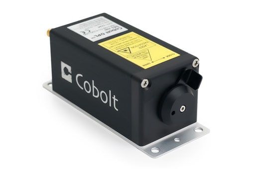
Fig. 20 Cobolt laser#
Lenses#
The lenses used are specific to the setup and depend on the distances the light needs to travel. In our setup, each excitation path has one scan lens and a tube lens. With the addition of another tube lens for the acquisition path.
Objectives#
The setup has a total of 3 objectives, 2 for the excitation path and one for the acquisition path:
4x 0.28 NA Objective (for excitation).
20x Objective (for collection).
Piezo-objective Positioner#
The piezoelectric objective positioner (see fig) is a component attached to the acquisition objective that moves vertically with a range of 600 micrometers. The piezo must be fast enough to be synched with the vertical galvanometric mirrors so that during the acquisition the distance between the objective and the light sheet does not change, thus, keeping the correct focus distance.
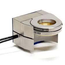
Fig. 21 Piezo-objective positioner from Piezosystemjana#
GFP filter#
The emission filter (see fig) simply filters out light coming at it with wavelengths outside of its working range. This allows it to filter out any unwanted light and to keep only the photons coming from the illuminated sample.

Fig. 22 GFP emission filter with a center wavelengh of 525 nm#
Stage#
To move the sample precisely in the optimal location we use a 3D moving stage (see fig). This allows for precise manual adjustment in x,y,z.
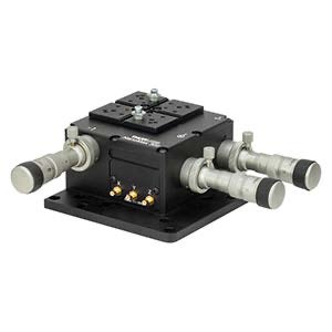
Fig. 23 Stage to precisely maneuver the sample chamber#
NI Board#
The Ni board (see fig) is a multifunction input/output device with multiple channels that allow for the independent triggering of single channels as well as synched output for multiple devices (e.g. the piezo and galvos waveforms). It is used to relay the control of the galvanometric mirrors, the piezo-objective positioner, and the camera trigger.
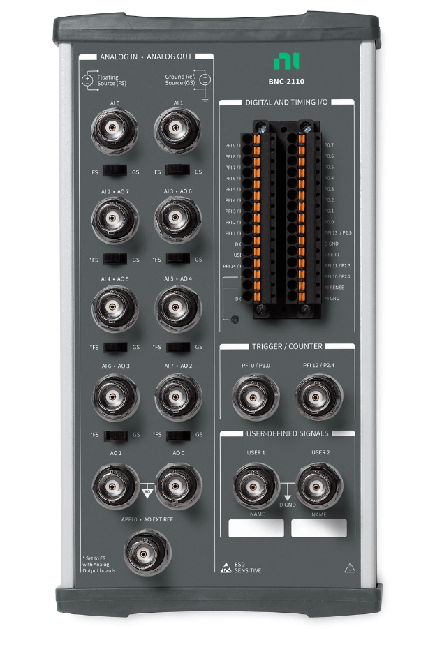
Fig. 24 Multi I/O NI board#
Parts list#
Warning
UNDER CONSTRUCTION
                               ___
                       /======/
               ____    //      \___
               | \\  //
       |_______|__|_//
       _L_____________\o
     __(CCCCCCCCCCCCCC)____________